|
|
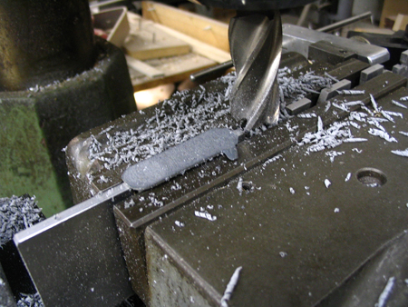
The back face of each bobbin half is flattened in the milling machine, holding it in an aluminum fixture in the vise.
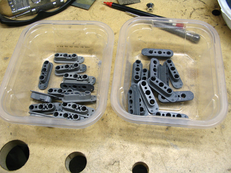
Finished batches of bobbin halves. The ones on the left are the top halves, which have the recesses and holes for the terminal wires. The bottom halves, on the right, only have the holes for the magnets.
The bobbin halves are assembled onto the magnets. I drill the bobbins to be a light press fit on the magnets, so the assembly stays together during winding.
Two 4-40 machine screws hold the assembly securely to the coil winder spindle.
|
|
|
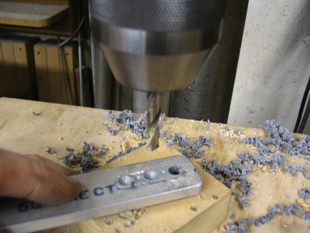
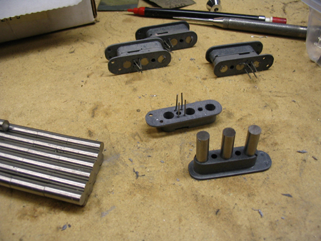
The holes for the magnets and terminal wires are drilled in the drill press, locating on the cast-in centering spots. I made up a simple aluminum bar tool to hold on to the bobbins while drilling.
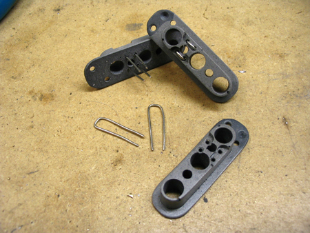
The terminals are small U-shaped loops of buss wire, which go through pairs of holes in the bobbin. These provide mechanically solid posts to solder the magnet wire and input leads to. This is important to prevent future pickup failures due to fractured wires.
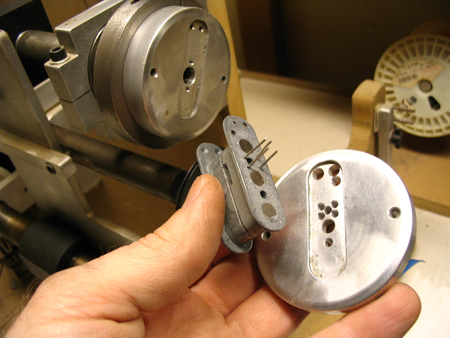
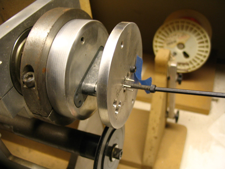
I built the spindle of my coil winder to mount interchangeable aluminum disks that I make up for each bobbin size. The M-pickup bobbin is sandwiched between this pair of disks, which have machined recesses to fit the bobbin's flanges. The disks help to guide the wire and prevent accidental loose loops from snagging on the spinning flanges.
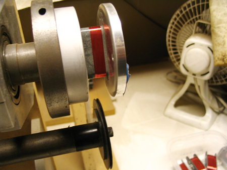
Starting the winding. The wire is too fine to see in this picture, but it passes around the black feed pulley and onto the bobbin. The feed pulley's side to side motion is mechanically synchronized to the spindle, to wind in tight flat layers.
Next Page..
|
|